

Sizing a GRP sectional tank for fire protection is not simply a matter of multiplying a nominal flow rate by a standard number of minutes. The correct approach is to establish the applicable fire protection design standard, determine the hydraulic water demand, establish the required duration, identify the usable water level of the tank, and then convert the required effective volume into an actual GRP sectional tank configuration.
The basic engineering relationship is:
Required Effective Fire Water Volume = Design Flow Rate × Required Duration
In practice, the ordered tank capacity may need to be greater than this calculated effective volume because the lowest usable water level, outlet arrangement, pump suction requirements, internal clearances and project-specific reserve requirements can reduce the portion of the geometric tank volume that is actually available to the fire pump.
This guide explains the sizing process with a worked engineering example, a comparison of major NFPA and BS references, and a practical GRP sectional tank selection method for EPC and fire protection projects.
For a fire suppression system, start with the required system water demand rather than the physical tank dimensions.
The important distinction is between geometric capacity and effective fire-fighting capacity.
| Term | Meaning | Why It Matters |
|---|---|---|
| Geometric Capacity | Total physical volume inside the tank | Defines the physical tank size |
| Effective Capacity | Water volume available to satisfy the fire system demand | Used for fire water sizing |
| Dead Storage | Water below the lowest level that can be reliably used for the intended fire demand | May make part of the geometric volume unavailable |
| Freeboard | Vertical space above the operating water level | Should not be counted as stored water |
| Reserve | Additional project-specific volume beyond the calculated demand | May be required by the project, authority or design philosophy |
One of the most common mistakes in online fire tank sizing content is treating NFPA 22 as though it provides one universal tank capacity for every fire protection application.
That is not a reliable engineering approach.
NFPA 22 is the Standard for Water Tanks for Private Fire Protection. The fire water demand itself may come from the applicable system design standard and hydraulic calculation. For example, NFPA 13 addresses automatic sprinkler system design and includes water supply requirements that vary with the system and hazard being protected.
Therefore, the correct relationship is better represented as:
Fire Protection System Design → Hydraulic Demand → Required Duration → Effective Tank Capacity → Tank Geometry
This distinction is particularly important for EPC projects. A tank supplier should not select a tank solely from a building floor area or a generic “fire tank size chart” without receiving the actual fire system design basis.
The starting point for a simplified fire water storage calculation is:
Veffective = Q × t
Where:
If the design flow is given in litres per second:
V (L) = Q (L/s) × t (s)
If the design flow is given in gallons per minute:
V (gal) = Q (GPM) × t (min)
For conversion to cubic metres:
V (m³) = Q (L/s) × t (s) ÷ 1000
This calculation is deliberately simple. The difficult part is not multiplying two numbers. The difficult part is determining what Q and t should actually be for the specific fire protection system.
The design flow rate should come from the approved fire protection hydraulic calculation rather than from the tank manufacturer's preferred capacity.
Depending on the project, the demand may involve sprinkler discharge, hose stream allowances, hydrant or standpipe requirements, water spray systems, or other fire protection demands. Whether multiple demands must be combined depends on the applicable standard and project design basis.
Therefore, the first RFQ question should not be:
“How many cubic metres should the GRP tank be?”
A better question is:
“What is the approved fire water demand at the tank/pump suction, and for how long must it be maintained?”
| Input | Example Value | Source to Confirm |
|---|---|---|
| Sprinkler demand | 500 GPM | Hydraulic calculation |
| Hose/standpipe allowance | 250 GPM | Applicable fire code/design standard |
| Combined design demand | 750 GPM | Approved fire protection design |
| Required duration | 60 min | Applicable standard/project requirement |
The values above are an illustrative engineering example only, not a universal NFPA requirement.
Water supply duration is one of the most misunderstood parts of fire tank sizing.
A statement such as “fire tanks require 90 minutes” is incomplete because the required duration depends on the type of protected system, occupancy or hazard classification, system configuration and applicable standard.
For example, published NFPA 13 material includes different water supply durations for different sprinkler applications. One NFPA 13 table for pipe-schedule systems shows 30 or 60 minutes for light hazard and 60 or 90 minutes for ordinary hazard, illustrating why a single universal duration should not be applied to every project.
Higher-hazard or special storage applications can require different design durations.
The correct EPC workflow is therefore:
Consider the following hypothetical project:
First calculate the total design flow:
Q = 500 + 250 = 750 GPM
Then calculate the required effective storage:
V = 750 × 60 = 45,000 gallons
Converting to cubic metres:
45,000 × 0.003785 = 170.3 m³
Therefore, the simplified hydraulic calculation indicates an effective fire water requirement of approximately 170.3 m³.
However, this does not automatically mean that a 170 m³ GRP sectional tank should be ordered.
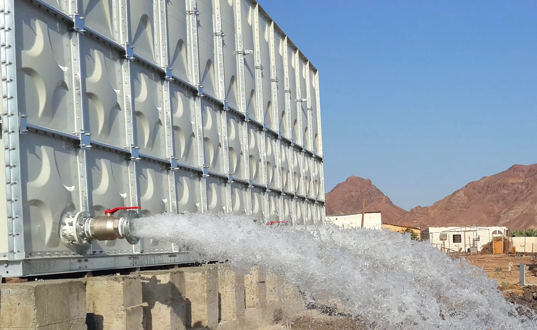
This is where tank sizing becomes an actual engineering exercise rather than a simple online calculator.
A sectional tank has physical dimensions, internal components, operating levels and connections. The complete geometric volume may not be available as usable fire water.
A simplified relationship is:
Geometric Capacity ≥ Effective Required Capacity + Non-Usable Volume + Project Reserve
The non-usable portion may include water below the minimum usable operating level established by the pump suction arrangement and tank design.
It is important to describe this correctly: “dead storage” is an engineering sizing concept, not a universal percentage that should simply be added to every fire tank.
The actual amount depends on the tank geometry, outlet arrangement, suction design, pump requirements and approved fire protection design.
Imagine a tank with a total internal height of 3.0 m. The calculated fire water volume may theoretically occupy the entire internal volume, but the fire pump may not be permitted to draw the tank completely dry.
Suppose the design establishes that the lowest usable water level is 0.25 m above the tank floor.
For an illustrative tank footprint of:
Length = 12 m
Width = 5 m
The theoretical volume below the 0.25 m usable level would be:
Vdead = 12 × 5 × 0.25 = 15 m³
If the required effective volume is 170.3 m³, the tank would need at least:
Vgeometric ≈ 170.3 + 15 = 185.3 m³
This is still a simplified calculation. The final tank should be selected using the actual water level, pump suction arrangement, tank dimensions and project requirements.
Important: Do not use a fixed “5% dead storage” or “10% dead storage” rule unless the applicable project specification explicitly requires it. Dead volume is a geometric and hydraulic issue, not a universal NFPA percentage.
Once the required effective capacity has been established, the next task is selecting practical tank dimensions.
For a rectangular sectional tank, the simplified geometric volume is:
V = L × W × H
Assume an illustrative configuration:
| Parameter | Example |
|---|---|
| Length | 12 m |
| Width | 5 m |
| Water depth | 3.1 m |
| Approximate geometric volume | 186 m³ |
The calculation is:
12 × 5 × 3.1 = 186 m³
If approximately 15 m³ is below the usable operating level, the simplified effective volume becomes:
186 − 15 = 171 m³
That is close to the illustrative 170.3 m³ requirement.
This demonstrates why a tank schedule should specify both nominal/geometric capacity and effective fire-fighting capacity where applicable.
| Step | Calculation | Result |
|---|---|---|
| 1. Sprinkler demand | Given by hydraulic calculation | 500 GPM |
| 2. Additional allowance | Project example | 250 GPM |
| 3. Total demand | 500 + 250 | 750 GPM |
| 4. Required duration | Project example | 60 min |
| 5. Effective volume | 750 × 60 | 45,000 gal |
| 6. Convert to m³ | 45,000 × 0.003785 | 170.3 m³ |
| 7. Illustrative unusable volume | 12 × 5 × 0.25 | 15 m³ |
| 8. Minimum geometric volume | 170.3 + 15 | 185.3 m³ |
| 9. Selected geometry | 12 × 5 × 3.1 | 186 m³ |
| 10. Approximate usable volume | 186 − 15 | 171 m³ |
This example is intentionally transparent: every number can be recalculated by an engineer reviewing the article.
It should not be treated as a universal warehouse fire tank specification. The actual project must use the approved hydraulic demand, applicable code, required duration and pump/tank arrangement.
For SEO content, it is tempting to write “NFPA 22 requires a fire tank of X m³.” That wording can be misleading.
A better way to understand the relationship is:
| Reference | Primary Role | Relationship to Tank Sizing |
|---|---|---|
| NFPA 13 | Automatic sprinkler system design | Helps establish sprinkler hydraulic demand and water supply requirements for applicable systems |
| NFPA 20 | Stationary fire pump installation | Relevant to pump selection and fire water supply interface |
| NFPA 22 | Water tanks for private fire protection | Defines requirements relevant to fire protection water tanks |
| NFPA 24 | Private fire service mains | Relevant to tank-to-system piping interfaces and private fire mains |
In other words, NFPA 22 should not be isolated from the hydraulic design when sizing the tank.
The term “BS compliance” can also hide an important distinction.
BS EN 12845 addresses automatic sprinkler systems, including water supplies, components, installation, testing and maintenance. BS 9251:2021 is specifically a code of practice for fire sprinkler systems in domestic and residential occupancies. It should not simply be substituted for BS EN 12845 on a warehouse, industrial plant or general commercial project.
| Reference | Main Application | Tank Sizing Relevance | Use Carefully |
|---|---|---|---|
| NFPA 13 | Automatic sprinkler systems | Hydraulic demand and water supply requirements | Requirements vary by system and hazard |
| NFPA 22 | Fire protection water tanks | Tank design and installation requirements | Does not replace hydraulic demand calculation |
| BS EN 12845 | Automatic sprinkler systems | Water supply and sprinkler design framework | Use the edition specified by the project/authority |
| BS 9251:2021 | Domestic and residential sprinkler systems | Residential fire sprinkler water supply | Not a generic commercial/industrial sprinkler standard |
The current BSI information identifies BS EN 12845:2015+A2:2026 as the current release, while BS 9251:2021 remains a current residential/domestic code of practice. Always confirm the edition and project adoption requirements before issuing a compliance statement.
Ninety minutes is a real value that appears in some fire sprinkler design scenarios, but that does not make it a universal fire tank duration.
For example, published NFPA 13 committee material shows 90-minute duration in specific storage protection design criteria. Other systems and hazard classifications use different durations.
Therefore, the article's calculation method should be:
Approved Design Demand × Approved Duration = Required Effective Fire Water Volume
This is much more defensible than writing:
“NFPA requires all fire tanks to store two hours of water.”
Such a blanket statement should be avoided in technical content.
Another common mistake is using the fire pump's rated flow directly as the tank design flow without checking the approved hydraulic calculation.
The tank, pump and distribution system must work as one hydraulic system.
Fire Hazard → Sprinkler/Hydrant Demand → Hydraulic Calculation → Pump Duty → Tank Effective Capacity
The pump must provide the required flow and pressure at the system demand point. The tank must provide enough usable water for the required duration under the approved design conditions.
Therefore, tank capacity should not be selected independently from pump duty.
Increasing tank height is one way to increase storage capacity without expanding the footprint.
For a rectangular tank:
Volume = Footprint Area × Water Depth
This means a compact footprint can produce a large storage volume by increasing water depth.
However, increased water depth also increases hydrostatic pressure on the lower tank panels.
P = ρgh
Where:
Therefore:
Higher Tank → Greater Water Depth → Higher Hydrostatic Pressure → Greater Panel/Connection Demand
This is why selecting the smallest footprint is not automatically the best structural solution.
PIPECO's existing technical discussion of GRP tank capacity also explains the relationship between water depth, hydrostatic pressure and tank configuration.
Read more about GRP water tank capacity and hydrostatic pressure.
Once the required capacity is known, the engineer must determine a practical modular configuration.
| Design Factor | Why It Matters |
|---|---|
| Tank footprint | Determines site utilization and foundation dimensions |
| Tank height | Determines water depth and hydrostatic pressure |
| Panel dimensions | Affect transportation, handling and structural behavior |
| Internal tie-rods | Transfer internal loads between panels and stabilize the tank structure |
| External reinforcement | May be required for larger tanks or project-specific structural conditions |
| Outlet arrangement | Controls how the stored water is delivered to the fire pump/system |
| Foundation/support | Transfers tank and water loads safely to the building or ground |
| Access | Required for inspection and maintenance |
GRP sectional construction is particularly useful when the required storage volume is large but site access is restricted. Individual panels can be transported into buildings or through constrained access routes and assembled on site.
The choice of a GRP sectional tank should be based on project requirements rather than marketing claims.
These benefits do not eliminate the need for structural design, hydraulic verification or proper installation.
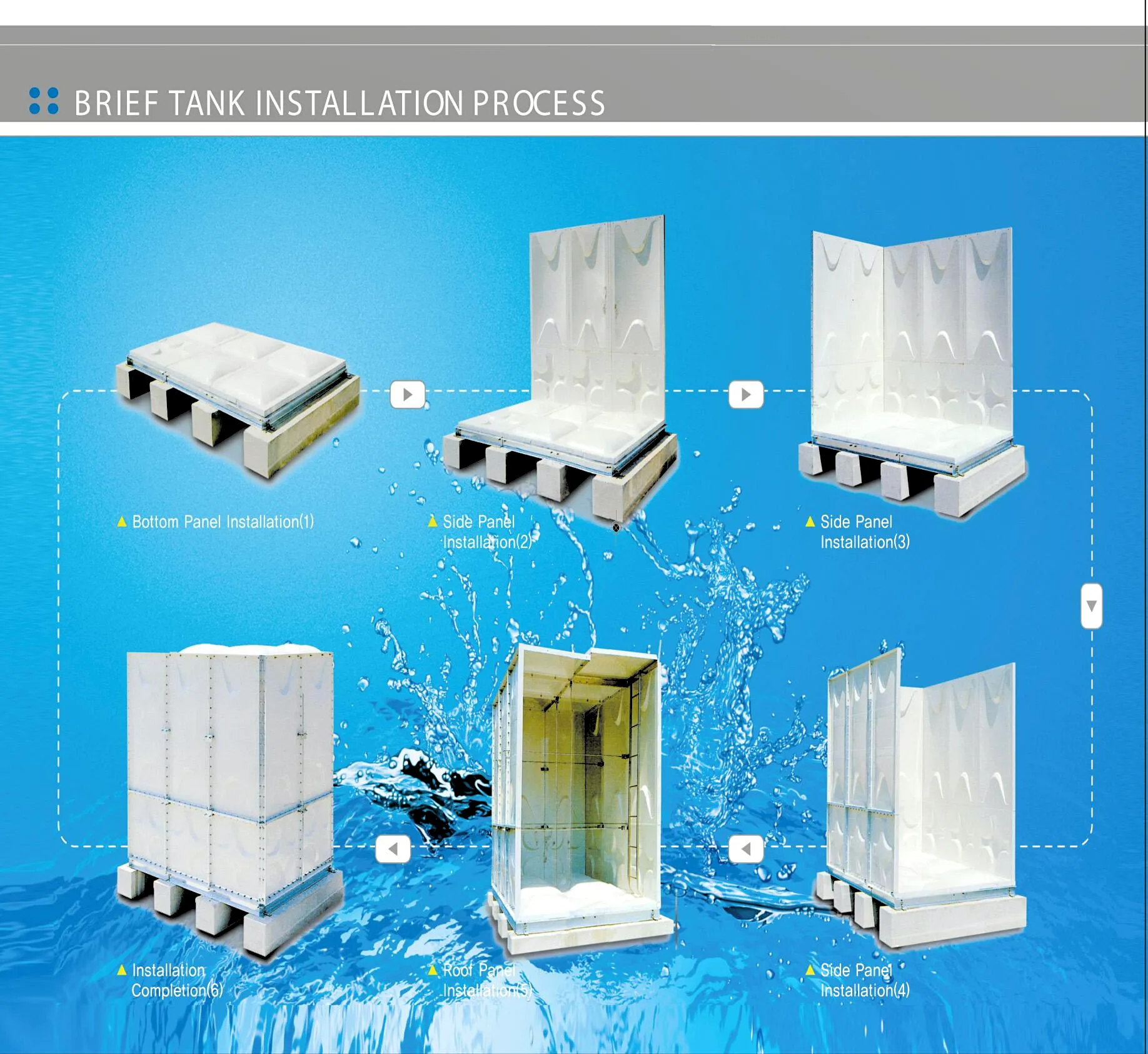
A tank may have enough total water volume on paper and still fail to satisfy the intended fire protection design if the outlet and suction arrangement is poorly configured.
The tank design should therefore consider:
A nozzle is therefore not simply a hole cut into a GRP panel. It becomes part of the structural and hydraulic interface between the tank and the fire protection system.
For detailed nozzle considerations, see: GRP Water Tank Nozzle Design: Inlet, Outlet, Drain and Overflow Connections.
A good fire tank RFQ should avoid giving the supplier only a nominal capacity such as “180 m³ fire tank.”
A more useful specification is:
| RFQ Item | Example Requirement |
|---|---|
| Tank application | Emergency fire protection water storage |
| Applicable standard | Project-specified NFPA or BS/EN standard |
| Design flow | 750 GPM illustrative example |
| Required duration | 60 minutes illustrative example |
| Required effective volume | 170.3 m³ illustrative calculation |
| Nominal/geometric volume | To be selected after usable-volume verification |
| Tank dimensions | To be confirmed by supplier engineering |
| Panel material | GRP/SMC according to approved specification |
| Internal support | Project-specified stainless steel system where applicable |
| External reinforcement | As required by structural design |
| Fire pump connection | According to approved pump and piping layout |
| Inspection | Project-specific FAT and documentation |
Building area alone does not provide enough information to determine fire water demand. Hazard classification, sprinkler design, system type and hydraulic calculations are required.
Water supply duration depends on the applicable system and design criteria. It should be documented rather than assumed.
NFPA 22 addresses fire protection water tanks. The system water demand may depend on other applicable NFPA standards.
A nominal tank volume does not automatically equal usable fire water volume.
The pump suction arrangement and minimum usable water level can affect effective capacity.
Greater height increases storage per unit footprint but also increases hydrostatic pressure.
Outlet size, location, suction arrangement and pipe loads must be coordinated with the fire pump system.
A professional compliance statement should identify the applicable standard, edition, project design basis and scope of compliance.
| Question | Confirmed? |
|---|---|
| What fire protection standard applies? | □ |
| What edition of the standard is specified? | □ |
| What is the hydraulic design flow? | □ |
| Are sprinkler and hose/standpipe demands combined? | □ |
| What is the required water supply duration? | □ |
| What is the required effective water volume? | □ |
| What is the lowest usable water level? | □ |
| Has dead/non-effective volume been considered? | □ |
| What geometric capacity is required? | □ |
| What are the maximum permitted tank dimensions? | □ |
| What is the required tank height? | □ |
| Has hydrostatic pressure been checked? | □ |
| Has the foundation been designed for full tank load? | □ |
| Has the fire pump suction been coordinated? | □ |
| Are inlet, outlet, drain and overflow connections defined? | □ |
| Are internal and external reinforcement requirements defined? | □ |
| Are material and component certificates required? | □ |
| Is FAT required before shipment? | □ |
For an EPC project, the tank calculation should not end with a quotation.
A technical submittal should normally be capable of showing how the quoted tank relates to the project requirement.
PIPECO's factory acceptance testing content provides additional background on how GRP tank dimensional, material, visual and documentation checks can be organized before shipment:
GRP Water Tank Factory Acceptance Test: Quality Inspection Before Shipment
For a project requiring a GRP sectional fire water tank, PIPECO can work from the project design basis rather than simply quoting a standard tank volume.
The engineering workflow can include:
For general product information, see: PIPECO GRP Water Tank.
Start with the approved fire protection design flow and required duration. A simplified calculation is V = Q × t. Then verify the usable water level, non-effective volume and any project-specific reserve before selecting the geometric tank capacity.
No. NFPA 22 is the standard for water tanks for private fire protection. The required water quantity is linked to the fire protection system design and applicable requirements rather than one universal tank volume for every building.
No. The required duration depends on the applicable fire protection system, hazard classification and project design criteria. Ninety minutes is applicable to some design scenarios but should not be treated as a universal requirement.
Effective capacity is the amount of stored water that can actually be used to satisfy the specified fire protection demand under the approved tank and pump arrangement.
Dead storage refers to water that is physically inside the tank but is not counted as available for the intended fire demand because it lies below the established usable operating level or otherwise cannot be reliably delivered to the fire system.
GRP sectional tanks can be engineered for fire water storage where the tank construction, components, capacity, connections, supports and project approvals meet the applicable requirements.
No. BS 9251 is a code of practice for fire sprinkler systems in domestic and residential occupancies, while BS EN 12845 addresses automatic sprinkler systems more broadly. The appropriate standard depends on the building and project scope.
Where the distinction is relevant, the RFQ should clearly state the required effective fire water volume and allow the supplier to demonstrate how the proposed geometric tank capacity provides that usable volume.
The fire protection design engineer normally establishes the system hydraulic demand. The tank supplier should use that approved design basis to develop the tank capacity and configuration.
Increasing height increases storage volume for a given footprint, but it also increases hydrostatic pressure on lower panels and connections. The tank structure therefore needs to be checked for the selected water depth.
The most reliable way to size a GRP sectional tank for emergency fire suppression is to work backwards from the fire protection design.
Fire Protection Demand
↓
Required Flow Rate
↓
Required Duration
↓
Effective Fire Water Volume
↓
Usable Water Level / Dead Storage Check
↓
Geometric GRP Tank Capacity
↓
Tank Dimensions + Structural Design + Pump Connections
This approach is more useful than a generic “NFPA fire tank size chart” because it exposes the engineering assumptions behind the final tank capacity.
For EPC projects, the key question is therefore not simply: “How many cubic metres is the tank?”
The better question is: “How much effective fire water must the system deliver, for how long, and how does the proposed GRP sectional tank demonstrate that capacity?”
Need custom GRP tank calculation for your EPC project? Contact PIPECO engineering team at master@pipeco.cn for a complete RFQ package.
PIPECO can support GRP sectional tank configuration, capacity verification, nozzle coordination, structural requirements and project-specific documentation for fire water storage applications.
Experience the brand Trusted by Renowned Companies across the GLOBE.
Pipeco stands at the forefront of the market, recognized as a premier manufacturer, supplier, and exporter specializing in top-tier GRP water tanks, stainless steel water tanks, and FRP Water Tank, Fiberglass Tank, SMC Water Tank committed to delivering unparalleled quality and excellence.
Get In Touch
Email: master@pipeco.cn
Tel: 0086-576-84616026
Address: No.2 Zhaofeng Road, Xinqian Street, Huangyan District, Taizhou City, Zhejiang Province, China