

GRP water tank nozzle design is an important part of sectional tank engineering. The nozzle is not simply a hole with a pipe connection. Its location, diameter, flange arrangement, reinforcement, sealing method and relationship with the tank structure can directly affect installation, maintenance and long-term operating reliability.
For a modular GRP tank, connection points normally include the water inlet, outlet, drain, overflow and sometimes additional connections for level sensors, firefighting systems, circulation lines or other project-specific equipment.
A reliable nozzle arrangement therefore needs to coordinate the tank panel structure, pipework, hydraulic requirements and site installation conditions rather than designing each connection independently.
This guide explains the key engineering considerations for GRP water tank nozzles, including connection location, pipe loads, flange interfaces, inlet and outlet arrangements, drain design, overflow connections and inspection requirements.
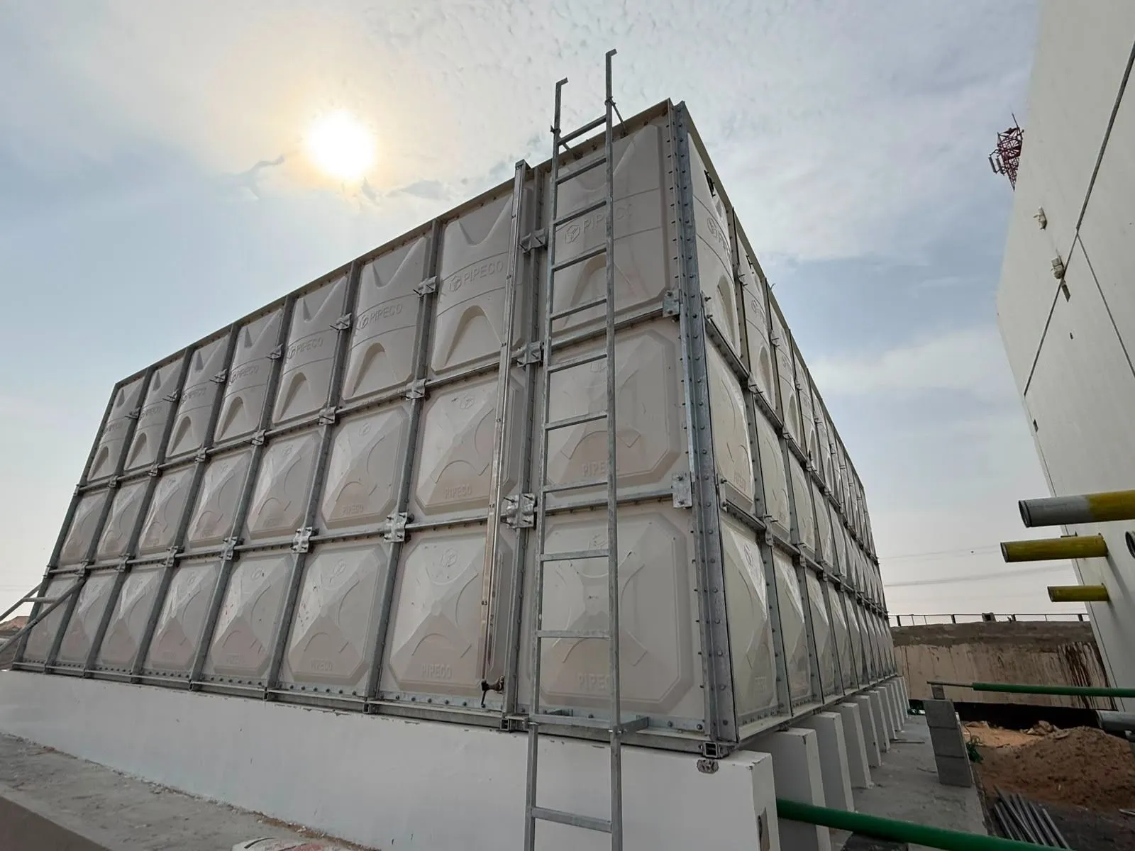
In a sectional GRP water tank, a nozzle is a prepared connection point through which water enters or leaves the tank, or through which auxiliary piping and instrumentation can be connected.
Depending on the project, nozzle assemblies may be installed on side panels, bottom panels or other designated tank locations.
Typical tank connections include:
The exact configuration depends on the tank's purpose and the connected piping system. A domestic water storage tank, industrial storage tank and fire-water tank may therefore require substantially different nozzle arrangements.
For an overview of sectional tank construction and components, see GRP sectional tank design and construction .
The connection between a tank and an external pipe creates a transition between two different structural systems.
The tank must contain hydrostatic water pressure while the connected piping system may introduce additional loads caused by its own weight, thermal movement, vibration, installation tolerances or operational forces.
This creates an important engineering principle:
A tank nozzle should be designed for both hydraulic connection and structural compatibility.
If a nozzle is correctly sized for water flow but the connected pipe is poorly supported, excessive external loading can be transferred into the tank panel or flange connection.
Conversely, a structurally suitable connection can still create operating problems if its diameter, elevation or position does not match the hydraulic requirements of the project.
Nozzle location should be determined during the tank engineering and general-arrangement stage rather than after fabrication.
The designer normally needs to coordinate the nozzle position with:
This is particularly important when the available installation space is restricted. A nozzle that appears suitable on a standard tank drawing may become difficult to connect when the actual building columns, walls, pumps or pipe racks are considered.
For projects requiring customized dimensions or connection positions, Pipeco's custom water tank solutions can be considered during the planning stage.
The inlet connection introduces water into the tank. Its design depends mainly on the required flow rate, inlet pipe size, water-entry velocity and internal tank arrangement.
The inlet should be positioned so that incoming water does not create unnecessary disturbance or interfere with internal components.
For some systems, the inlet may be located near the upper portion of the tank. Other configurations may require a different elevation because of hydraulic conditions or site pipework.
The inlet nozzle diameter should be coordinated with the connected pipe diameter and required water flow.
It should not be selected simply according to the nominal tank capacity. A relatively small tank operating at a high filling rate can require a larger connection than a larger tank operating at a low flow rate.
Therefore, the engineering inputs should include the specified filling flow rate and the connected piping system before the nozzle size is finalized.
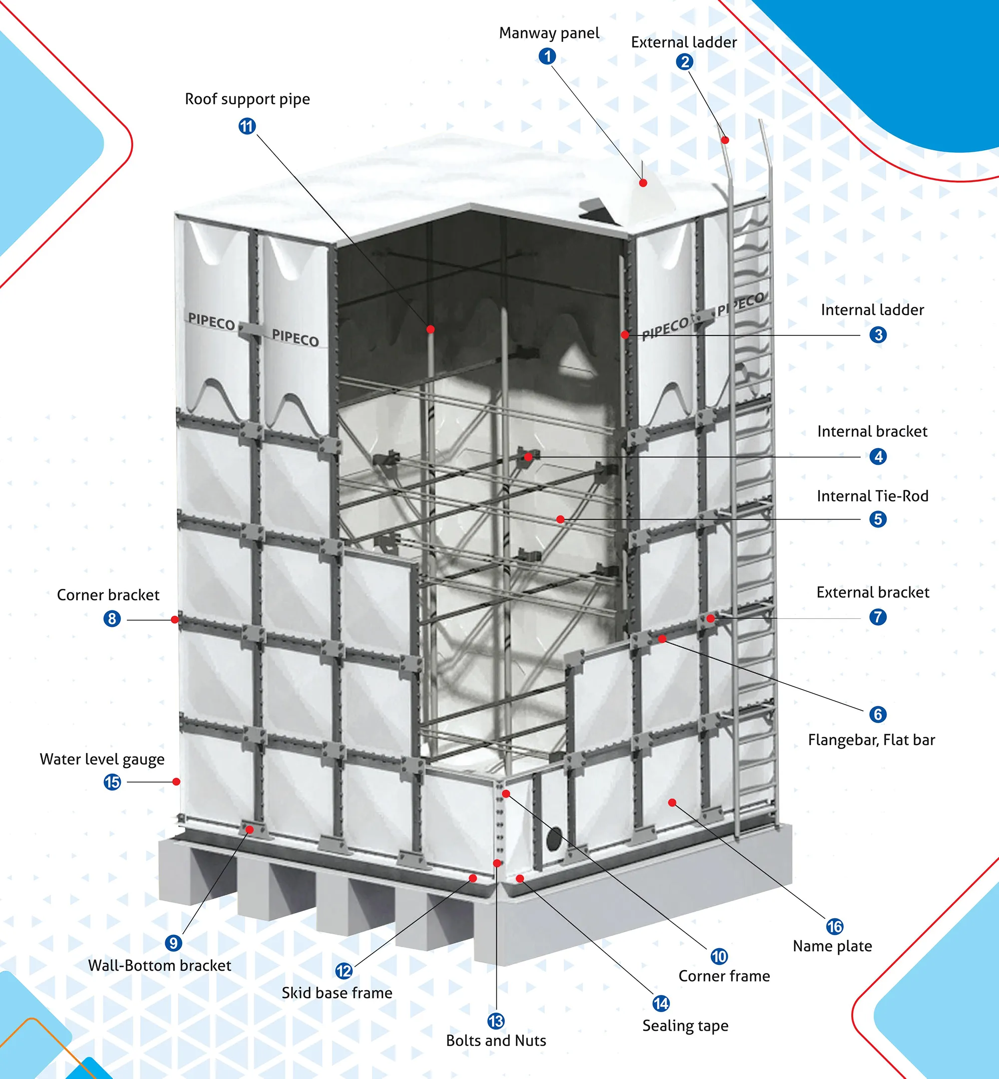
The outlet is often one of the most important connections because it may be connected directly to a pump, distribution header or process pipeline.
The outlet elevation must provide the required operating condition while maintaining compatibility with the external pipe system.
The engineer should consider:
If a pump is connected to the tank outlet, the complete suction arrangement should be reviewed rather than considering the tank nozzle independently.
Incorrect outlet elevation can affect usable tank volume, pump operating conditions or maintenance access even when the tank itself is structurally sound.
One of the most important considerations in nozzle design is that the tank should not be expected to carry the full weight of the external piping system.
Large-diameter pipes can be heavy, particularly when filled with water. Valves, strainers, meters, expansion joints and other fittings can add further loads.
If these loads are transferred directly to the tank nozzle, they can create local stresses around the connection.
The basic engineering approach is therefore:
Support the external pipework independently and minimize unnecessary mechanical loading on the tank connection.
Pipe supports, flexible connections and suitable installation clearances can help separate external piping loads from the tank structure.
The exact support arrangement should be determined by the project engineer according to pipe size, material, operating conditions and site layout.
Flanged connections are commonly used where the tank needs to connect to external pipework through a bolted interface.
The flange arrangement should match the connected pipe system in terms of nominal diameter, drilling pattern, bolt configuration and sealing requirements.
A flange mismatch can create unnecessary installation work or require field modifications that were not included in the original engineering design.
These dimensions should be confirmed against the approved project drawings before production.
A nozzle connection must maintain a reliable seal throughout normal tank operation. This means that gasket selection and flange assembly are just as important as the flange dimensions themselves.
The sealing system should be compatible with:
During assembly, bolts should be tightened in an appropriate sequence so that the gasket is compressed evenly.
Excessive tightening can be just as undesirable as insufficient tightening. The final assembly method should follow the applicable project specifications and component manufacturer's requirements.
The drain connection allows the tank to be emptied for inspection, cleaning, maintenance or emergency operations.
A drain that is technically present but poorly located may leave a significant quantity of water inside the tank. Therefore, drain elevation and floor geometry should be considered together.
Where practical, the drain should be positioned to support effective tank emptying while remaining accessible for operation and maintenance.
The surrounding foundation and external drainage system must also be considered. Discharging a large tank volume into an inadequately sized drainage area can create secondary site problems.
Drain connections should therefore be coordinated with the complete tank installation plan, not specified as an isolated component.
For broader installation considerations, see how to install a GRP water tank .
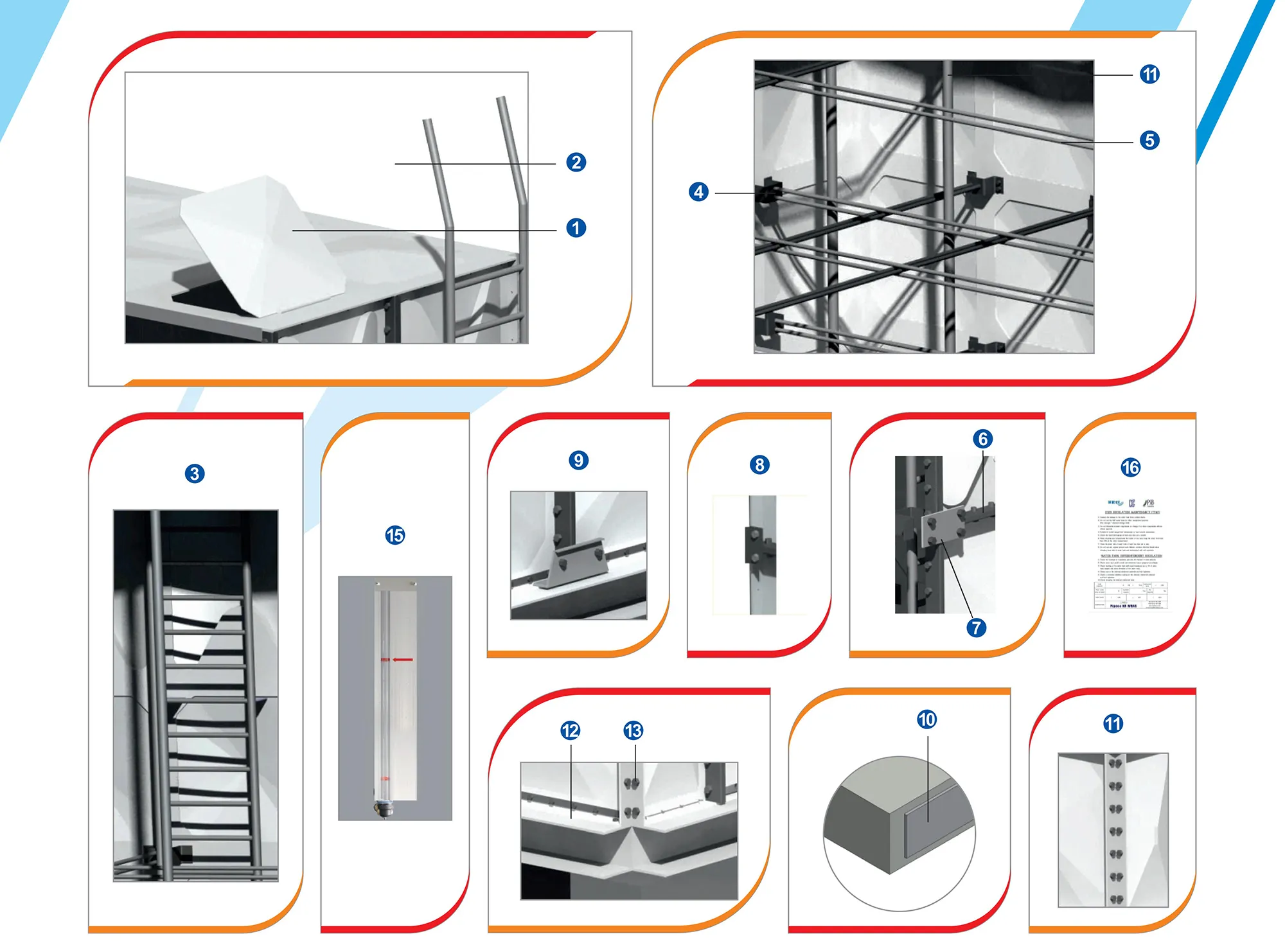
The overflow connection provides a controlled route for water when the tank level rises above the intended operating level.
Overflow design should consider the maximum possible inflow and the downstream discharge route.
The overflow elevation is also important because it effectively establishes the upper water level that the tank system is intended to control.
The overflow should be coordinated with the tank ventilation system because the two components have different functions.
In particular, the overflow should not simply be treated as a substitute for the dedicated tank vent.
For a detailed explanation of this distinction, see the related guide on GRP water tank ventilation, air inlet and overflow design .
Nozzle elevation can influence the actual usable water volume of a tank.
For example, an outlet positioned significantly above the tank floor may leave a residual volume that cannot be removed through normal operation. Similarly, an incorrectly positioned overflow can reduce the effective operating level.
This is why the relationship between tank dimensions, water level and connection elevations should be reviewed during the design stage.
The nominal tank capacity and the practical usable capacity are not always identical.
For projects where storage volume is critical, the connection elevations should be reviewed together with the GRP water tank capacity calculation .
GRP sectional tanks can use different connection arrangements depending on the project design.
| Connection Location | Potential Application | Important Considerations |
|---|---|---|
| Side panel | Inlet, outlet, overflow and other pipe connections | Pipe support, flange access and panel reinforcement |
| Bottom area | Drain or selected outlet arrangements | Foundation clearance and local structural loading |
| Upper tank area | Selected inlet, overflow or auxiliary connections | Water level, access and roof arrangement |
There is no universal nozzle location suitable for every project. The final arrangement should be based on hydraulic requirements, tank construction, connected piping and site conditions.
The external piping system should normally be supported independently of the GRP tank wherever practical. This is particularly important for large-diameter connections and pipelines containing a significant volume of water.
A pipe connected to a tank can impose several types of load, including:
The purpose of external pipe supports is to control these loads before they are transferred to the tank connection.
This principle becomes increasingly important as pipe diameter increases. A small connection and a large pipe header should therefore not be treated as the same engineering problem.
A nozzle creates a local opening in the tank panel. The surrounding panel must continue to perform its structural function while accommodating the connection.
The engineering assessment may therefore need to consider the relationship between:
The objective is to avoid concentrating unnecessary stress around the opening.
This is especially relevant when a large nozzle is positioned close to a panel edge, corner, flange or another penetration.
The panel manufacturing process also matters because the finished connection must retain the dimensional and structural characteristics required by the approved design.
For additional information about GRP panel production and quality control, see how GRP water tank panels are manufactured .
A nozzle may appear to be located correctly from the outside but still interfere with components inside the tank.
Depending on the tank design, internal elements may include structural supports, tie systems, partitions or other components.
The designer should therefore verify the internal clearance around each connection before finalizing the nozzle position.
A connection should not unintentionally obstruct:
For large sectional tanks, nozzle coordination is therefore part of the overall tank layout rather than a separate piping detail.
When the tank stores potable water, nozzle design must consider both mechanical performance and hygienic requirements.
The connection system should be compatible with the intended water service, while the internal arrangement should minimize locations where stagnant water, debris or difficult-to-clean areas could develop.
Particular attention may be required for:
The applicable potable-water requirements should always be confirmed for the target country, project and water-storage application.
Buyers comparing different tank materials can also review Pipeco's water tank material selection guide when determining which tank configuration is appropriate for the project.
Fire-water storage systems can require multiple connections and relatively high flow rates. The inlet, outlet, overflow and drain arrangements should therefore be coordinated with the complete firefighting system.
The tank connection schedule should be checked against the approved fire protection design, including the required pipe sizes, elevations and connection locations.
The tank itself should not be treated as an isolated component because downstream pumps, suction piping, valves and other equipment can influence the final connection arrangement.
For projects involving fire-water storage, see the related GRP firefighting water storage information and the separate GRP tank and NFPA-related fire-water design discussion .
The drain connection becomes particularly important during periodic cleaning and inspection.
If the drain is poorly positioned, the tank may retain a considerable quantity of water after normal draining. Operators may then need additional manual pumping or removal procedures.
A practical drain design should therefore consider:
The drain connection should also be protected from accidental mechanical damage during installation and operation.
Proper drainage works together with the tank's overall maintenance program. More information is available in the GRP water tank maintenance guide .
Connection locations can have a significant effect on site installation efficiency.
A nozzle that is correctly manufactured but positioned incorrectly relative to the site pipework can create additional field modifications, adapters or pipe offsets.
Before manufacturing, the following information should therefore be confirmed:
For a detailed installation workflow, see how to install a GRP water tank .
For an EPC project, a nozzle schedule can provide a simple way to control connection information before manufacturing.
A typical schedule can include the following fields:
| Field | Example Information |
|---|---|
| Tag | IN-01 / OUT-01 / D-01 |
| Service | Inlet / Outlet / Drain / Overflow |
| Nominal Size | Project-specified pipe diameter |
| Connection Type | Flanged / other specified connection |
| Elevation | Center-line elevation from project datum |
| Orientation | Specified direction or tank side |
| Quantity | Number of identical connections |
| Design Flow | Applicable inlet or outlet flow |
| Remarks | Special gasket, valve or installation requirements |
Using a connection schedule reduces ambiguity between the tank supplier, piping engineer, civil contractor and installation team.
A supplier can design and manufacture tank connections more accurately when the buyer provides complete project information at the RFQ or engineering stage.
At minimum, the purchaser should consider providing:
For customized projects, providing the piping layout or connection schedule at the beginning of the engineering process can substantially reduce the possibility of field modifications.
Nozzle inspection should verify both dimensional conformity and physical condition before the tank leaves the factory.
Typical inspection items include:
| Inspection Item | What to Check |
|---|---|
| Nozzle size | Verify against approved drawings |
| Location | Check elevation and position |
| Flange | Check dimensions and bolt-hole arrangement |
| Surface | Check for visible defects or damage |
| Sealing components | Confirm specified gaskets and sealing parts |
| Reinforcement | Verify specified reinforcement arrangement where applicable |
| Orientation | Confirm connection direction |
| Documentation | Confirm inspection and quality records |
These checks can be incorporated into the overall GRP water tank factory acceptance test when FAT is specified by the purchaser.
Nozzle dimensions should not be controlled only by verbal communication or informal email descriptions. For custom tanks, the approved drawing should become the reference document for manufacturing and inspection.
The drawing should clearly identify:
Once the drawing has been approved, changes to nozzle positions should be controlled through the project's engineering change process.
This is particularly important when the tank has already entered fabrication because changing a connection after panel production can create additional engineering and manufacturing work.
A pipe diameter does not fully define a tank connection. Flange dimensions, elevation, orientation and connection standard may also be required.
Late changes can conflict with the panel arrangement and may require engineering review or modification.
The tank supplier may provide the nozzle, but the connected pipework still needs appropriate independent support.
A valve or flange that is technically accessible but physically difficult to operate can increase maintenance time.
Inlet, outlet, drain and overflow connections perform different functions and may have different hydraulic and installation requirements.
Adding major connections after the tank layout has been finalized can complicate fabrication and site installation.
Before approving a GRP sectional tank for production, the purchaser and engineering team can use the following checklist:
| Question | Status |
|---|---|
| Are all required inlet connections identified? | □ |
| Are all outlet connections identified? | □ |
| Is the drain location confirmed? | □ |
| Is the overflow location confirmed? | □ |
| Are connection diameters confirmed? | □ |
| Are flange standards confirmed? | □ |
| Are elevations and orientations confirmed? | □ |
| Is external pipe support considered? | □ |
| Are maintenance clearances available? | □ |
| Are nozzle details shown on the approved drawing? | □ |
| Are nozzle dimensions included in FAT inspection? | □ |
The main purpose of nozzle engineering is to create a reliable transition between the GRP tank and the external piping system.
The key relationship can be summarized as:
Hydraulic requirement → connection size → nozzle location → structural coordination → pipe support → sealing → inspection.
Each step affects the next. Selecting a nozzle size without checking the flow rate can create hydraulic problems. Selecting a location without checking pipe routing can create installation problems. Designing the connection without considering external pipe loads can introduce unnecessary mechanical loading.
For this reason, nozzle design should be completed as part of the overall GRP tank engineering package.
The most common connections are inlet, outlet, drain and overflow. Additional connections may be required for circulation, instrumentation, firefighting or other project-specific services.
The external piping should generally be independently supported so that unnecessary pipe weight, vibration and other mechanical loads are not transferred to the tank connection.
The nozzle size should be coordinated with the connected pipe and required flow conditions. Tank capacity alone does not determine the appropriate connection diameter.
Changes after fabrication may require engineering review and can involve additional modification work. Nozzle locations should therefore be finalized on approved drawings before production whenever possible.
Yes. Where FAT is specified, nozzle size, location, flange dimensions, orientation and other agreed connection details can be checked against the approved drawings and project specifications.
Drain elevation affects how effectively the tank can be emptied for cleaning, inspection and maintenance. It should be coordinated with the tank floor, foundation and external drainage system.
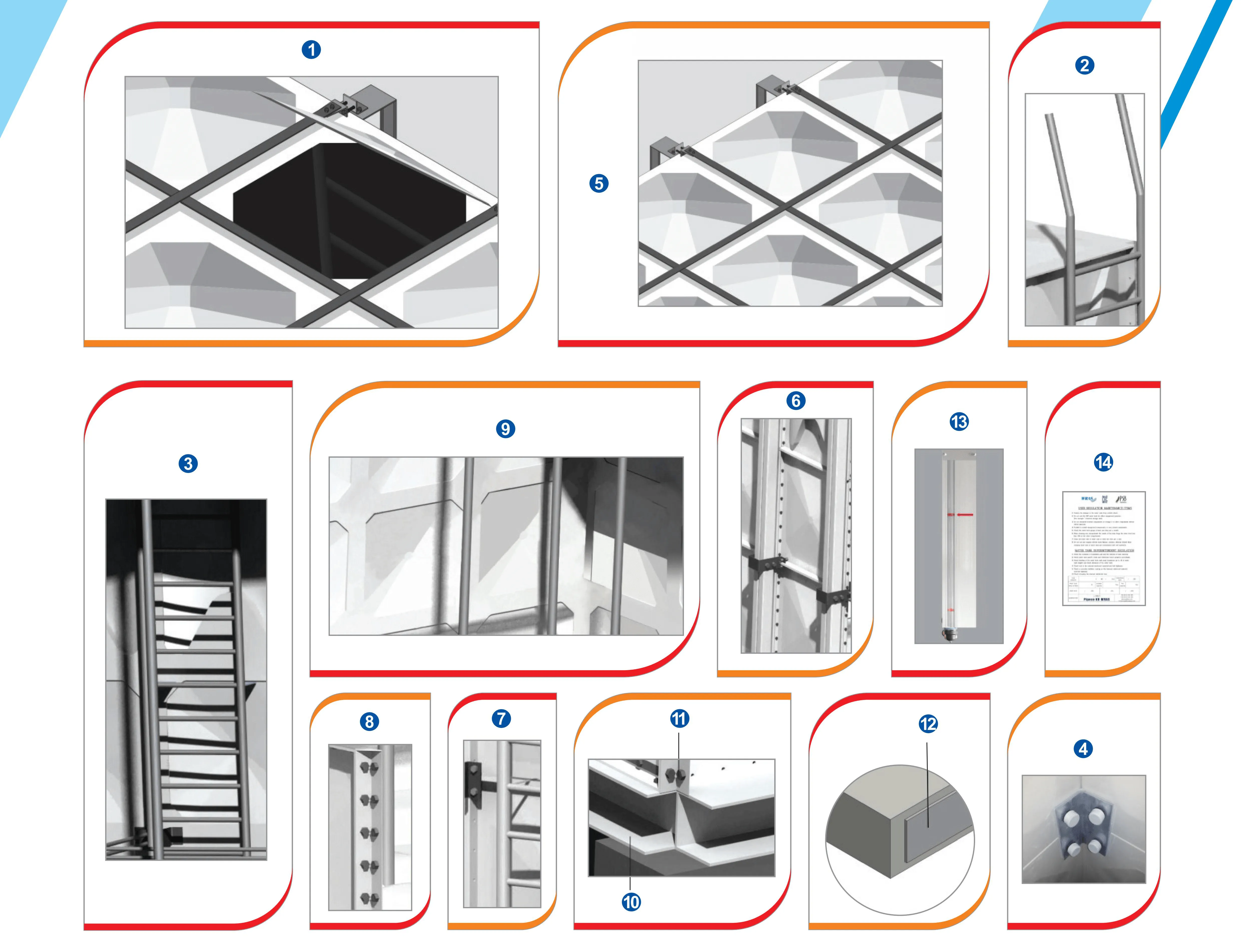
GRP water tank nozzle design is a combined hydraulic, structural and installation engineering task.
Inlet, outlet, drain and overflow connections should be selected according to the actual operating requirements of the project. Their dimensions, elevations, orientations and flange details should then be coordinated with the tank structure and external piping system.
Independent pipe support, appropriate sealing, sufficient maintenance clearance and drawing-based inspection are equally important. When these elements are addressed before fabrication, the risk of field modification and connection problems can be significantly reduced.
For a customized GRP sectional tank project, Pipeco can review tank capacity, dimensions, connection requirements and application conditions as part of the project specification process.
Contact Pipeco for GRP water tank engineering and project requirements .
Experience the brand Trusted by Renowned Companies across the GLOBE.
Pipeco stands at the forefront of the market, recognized as a premier manufacturer, supplier, and exporter specializing in top-tier GRP water tanks, stainless steel water tanks, and FRP Water Tank, Fiberglass Tank, SMC Water Tank committed to delivering unparalleled quality and excellence.
Get In Touch
Email: master@pipeco.cn
Tel: 0086-576-84616026
Address: No.2 Zhaofeng Road, Xinqian Street, Huangyan District, Taizhou City, Zhejiang Province, China